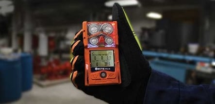
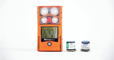
PID sensors play a key role in gas detection fleets for fire departments, municipalities, emergency response teams (ERT), and all sorts of industries that need a quick way to confirm the presence of volatile organic compounds (VOCs) in the atmosphere or to locate the source of a leak.
Before using a PID sensor to detect VOCs, you should understand how it works so you know what to expect.
Without further ado, let’s start with a quick lesson in chemistry (and physics).
The PID sensor targets gases at the molecular level, and molecules are a group of atoms linked together through bonds. The strength of these bonds is measured in electron volts (eV) and is referred to as the Ionization Potential (IP) of the molecule. This number can be found in the physical description of just about any gas. For example, propane has an IP of 11.07eV. Ammonia’s IP is 10.2eV., and toluene has an IP of 8.82eV.
This information is important because the IP of a given gas will indicate whether a PID sensor can detect its presence in the atmosphere.
So how does a PID sensor detect VOCs?
PID sensors contain an ultraviolet (UV) lamp that releases a certain energy from its photons. When that energy is strong enough, it will tear apart the bonds of the exposed molecule, which in turn will separate its atoms and transform them into positively charged ions. At the same time, electrons are discharged as a byproduct. Thus, the UV lamp has ionized the molecule with the energy of its photons. This chain reaction is appropriately called photoionization.  The PID sensor also contains a set of positive and negative electrodes. As we know: opposites
attract, so the positive electrode attracts the electrons (which are negatively charged) and the negative electrode attracts the positively charged ions (also known as protons). This creates a
small current that gets amplified and converted by the gas detector into a ppm (parts per million) reading.
Therefore, you need to know the energy of your PID lamp to identify what gases it will or will not
detect. Industrial Scientific PID sensors use a 10.6 eV lamp, which means that they can detect any gas that has an IP equal to 10.6 eV or less.
Calibrating a PID Sensor
Like any gas sensor, regular calibration is key to ensuring accurate readings from a PID sensor. But if the PID sensor is not specific to a single target gas, what gas is used to calibrate it? The standard choice is isobutylene, for two reasons:
- Isobutylene is not toxic or combustible at low concentrations.
- Isobutylene’s IP is situated at the midpoint of most VOCs.
This means that if a PID gas detector calibrated to isobutylene gas is exposed to a VOC or compound that has an IP of 10.6 eV or less, the gas detector will interpret the gas’s concentration as if it were isobutylene gas.
To know the true concentration of the actual gas that triggered the reading, you would have to multiply the gas detector’s reading by the targeted gas’s response factor (RF). With Industrial Scientific PID sensors used in the Ventis Pro5® Multi-Gas Monitor, it is possible to pre-program the gas detector to automatically apply the RF of a target gas, thus avoiding mental calculations.
Using a PID Sensor
Why have I troubled you with such a tedious, and dare I say, not so refreshing refresher?
It’s easy to look at the long list of unpronounceable gases that the PID sensor can detect, find the one obscure gas you need to target, and jump to the conclusion that the PID sensor is the right fit for you. What’s important to understand is that the PID sensor will ionize any gas that it is capable of ionizing, giving you a single cumulative reading of all those various gases. It cannot tell them apart, nor filter out some, nor filter some in. It will only tell you whether there is something in that atmosphere or not and help you locate the source of a leak.

PID Sensors in Action
A manufacturing plant uses large amounts of toluene as a solvent in its process. Staff have been notified of an abnormally strong odor. They suspect that there must be a toluene leak. The area is immediately evacuated, the site’s ERT is deployed to contain the spill, and the local fire department’s hazmat team has been summoned to help set-up the cold, warm, and hot zones and locate the source of the leak with their PID monitors.
As mentioned before, the IP of toluene is only 8.82 eV which means Industrial Scientific’s PID sensor will detect it. The hazmat team brings with them some Ventis Pro5 Multi-Gas Monitors containing several sensors, including a PID that has been calibrated to isobutylene gas. Given the emergency, they decide not to program the toluene response factor directly on their monitors. They know that the RF for Toluene gas is x0.56, so if the PID sensor displays 100 ppm, the user will know that there is approximately 100x 0.56 = 56ppm of toluene in the atmosphere. In this example, the response factor can be rounded down to half the value of the gas detector’s reading, which will make for easy math.
When the hazmat team arrives, the site’s ERT has successfully contained the spill. Now it’s time to establish the zones. Thanks to the nature of the PID sensor, its response time is instant. This makes it easy to identify whether one is heading toward the source of the leak or away from it. Using the Ventis Pro5 monitors, the hazmat team walks around the area, paying close attention to their PID sensor readings. One of them quickly identifies the hot zone because their readings suddenly spike. In fact, the PID sensor over-ranges. This indicates that the readings are above 2,000 ppm, which means there is more than 1,120 ppm of toluene in that area.
This is the time for another key sensor to shine: the ultra-low powered (ULP) hydrocarbon (HC) IR sensor. To put it simply, this sensor uses Infrared technology to detect the presence of hydrocarbons in the atmosphere. Measuring from 0 to 100% LEL, it provides an indication as to whether the area is at risk of combustion, playing a similar role as the classic catalytic diffusion sensor. The benefit of the ULP HC IR sensor is that it extends the battery life of the monitor, allowing the Ventis Pro5 to be configured with both a PID and a combustible gas sensor. It also doesn’t get damaged when regularly exposed to excessively high concentrations, or poisons and inhibitors.
Returning to the scene of the leak, the user moves further into the hot zone and the ULP HC IR sensor hikes up to 100% LEL. It, too, is now over-ranged, indicating that they must be getting close to the source. And right there along the underbelly of the toluene pipeline is a cracked section—the clear result of excess corrosion.
Because they are using Ventis Pro5 monitors, the hazmat team is linked together via LENS Wireless, allowing them to see their peer’s readings in real time on their own monitors. They notify the ERT, who set off to address the leak.

What becomes of the remaining toluene vapors that have not yet dissipated? The hazmat team deploys portable Radius® BZ1 Area Monitors that are not only equipped with PID sensors, but also have LENS Wireless capability just like the Ventis Pro5 personal monitors, allowing peer-to-peer communication across all the PID units in the field.
Taking into consideration wind direction, they strategically place the area monitors in a manner that will allow them to continuously track toluene levels in all zones. The ERT will also use Ventis Pro5 monitors until the hazard has fully cleared the atmosphere. Should one of the area monitors go into alarm, the LENS Wireless functionality will allow the Ventis Pro5 user to be immediately notified through their unit. In fact, they will have access to current gas readings of all Radius BZ1 Area Monitors and Ventis Pro5 Multi-Gas Monitors in the field.
Finally, as a final touch, the hazmat team has set up RGX gateways that will allow the equipment’s data to be sent directly to the cloud for remote live monitoring. The ERT and the control center can now monitor live readings on all gas detectors in the field from a browser and receive real-time alerts no matter how far they are from the site.
Once the issue is fully resolved, the fire department will collect their equipment and prepare it for the next call. After this experience, the manufacturing plant will likely choose to equip themselves with their own PID gas monitors should a case like this ever occur again at their site.
This example illustrates just how a PID sensor can be used. It also shines a light on how a tried-and-true sensor like the PID can keep up with the times and unlock new possibilities in the world of connected safety.
Learn more about detecting VOCs using Industrial Scientific’s PID sensor.


